 Introductory Digital Electronics - Logic Gates
Introductory Digital Electronics - Logic Gates Introduction -
Digital Signals and Logic Gates
Introduction -
Digital Signals and Logic Gates
 Basic Logic Gates
 Example
 Problem
 Go to Next Chapter or
Home Page
Go to Next Chapter or
Home Page
Digital Signals and Logic Gates Engineers know that it is easier to design devices than multi-state devices. In logic systems, variables, circuits, statements, etc., can be treated in one of two distinct states: true or false, yes or no, on or off, present or absent, energized or not energized, conducting or non-conducting, high voltage or low voltage, and so on.
In digital electronics, we distinguish two distinct values of voltage, VH corresponding to the higher of the two voltages and VL corresponding to the lower of the two voltages. There are three ways in which we can assign binary values to these voltages :
1. Positive logic assignment : 	True [ 1 ] : VH
				False [ 0 ] : VL

2. Negative logic assignment : 	True [ 1 ] : VL
				False [ 0 ] : VH

3. Mixed logic assignment : 	Allow the designers to use positive
				or negative logic at any point in
				their design, as they desire.
We shall use positive logic throughout this course. The description of the other two assignments can be found in elsewhere [Ref.1].
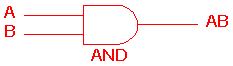
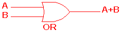
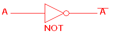
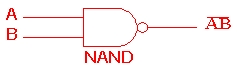
Basic Logic Gates All digital systems can be constructed by only three basic logic gates. These basic gates are called the AND gate, the OR gate, and the NOT gate. Some textbooks also include the NAND gate, the NOR gate and the EOR gate as the members of the family of basic logic gates. The description of the operations of these gates are listed below [Ref.2]:
 ) is used to indicate the
AND operation. In practice, however, the dot is usually omitted.
) is used to indicate the
AND operation. In practice, however, the dot is usually omitted.
 .
.
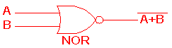
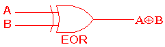
 ) is used to indicate the EOR operation.
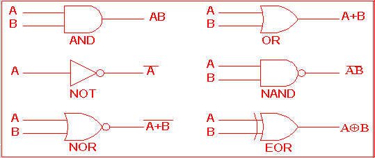
 Figure 1.1 Symbols for logic gates
The functions of these basic building blocks are summarized by
means of a Truth Table as shown in Table 1.1. The table
shows all possible input/output combinations for two inputs.
A truth table with n inputs (logic variables) has 2n rows.
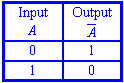
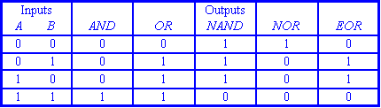
 Table 1.1 Truth table representation of logic gates
Example 1.1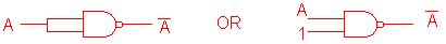 Problem 1.1
Click here to consult model answer.
Go to Next Chapter or
Home Page